PTC- Original Technologies and Trust
MAXMUM TECHNOLOGY
MAXMUM TECHNOLOGY
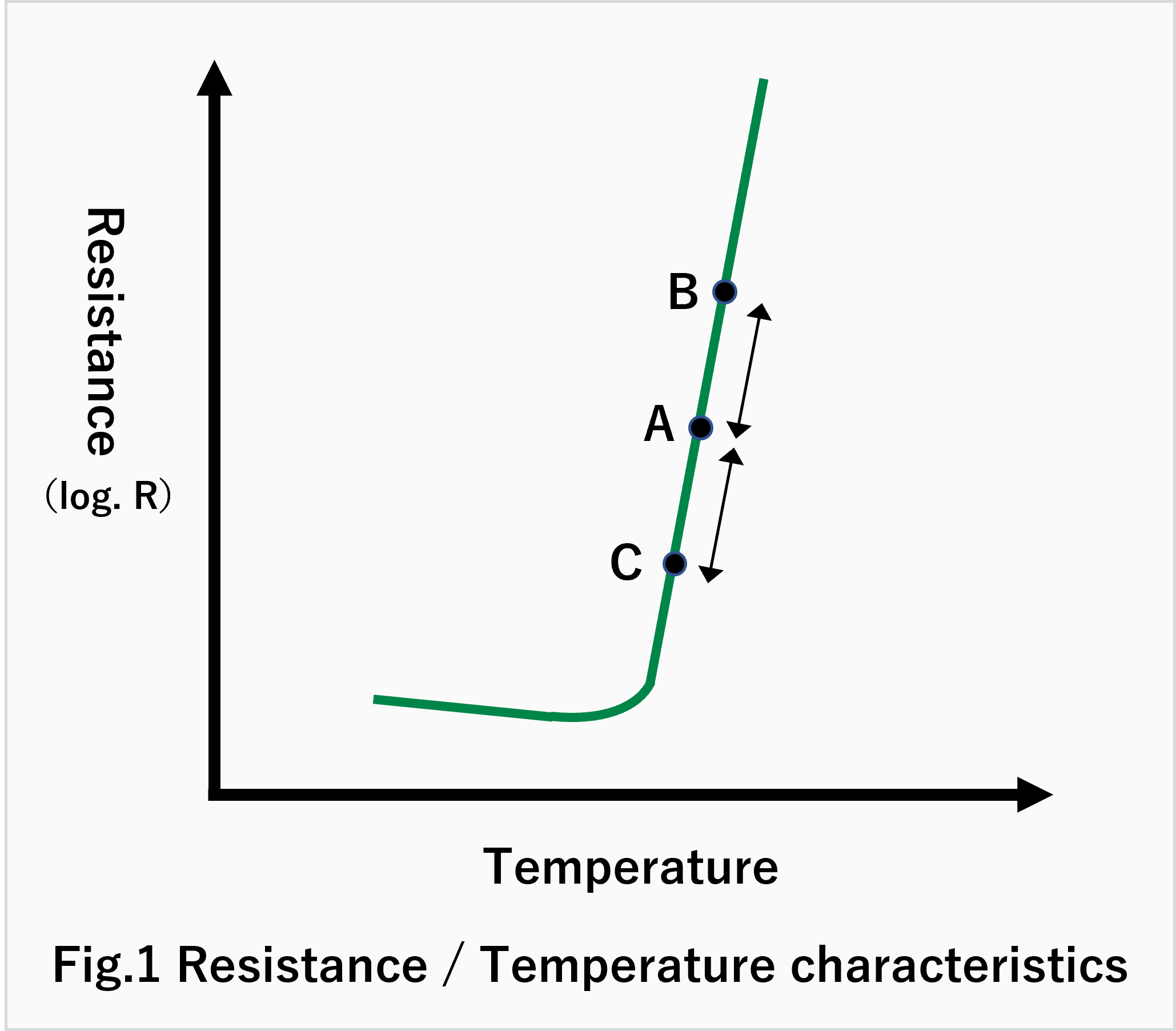
We would explain on Automatically Temperature Control Function with T-R Characteristics in Fig.1
Now, PTC is operated in steady state at point "A".
Under this circumstance, applied Voltage and/or ambient Temperature is to be increased, operating point is to be moved from A to B
and Resistance is to be increased by Temperature increase then Current become smaller , concequently, operating point would be backfrom B to A.
The other way around, in case applied Voltage and/or ambient Temperature is to be decreased,PTC temperature is to be decreased then operation point move to C, then PTC resistance is to be smaller according to Temperature decreasing, operating point back from C to A.
According to the above,almost the constant temperature is to be kept in spite fo any change of appling voltage and ambient Temperature.
Addition to the above, Automatical Temperature Control Function of PTC would be explained by Voltage-Current Characteristics in Fig.2 PTC shows almost the constant Electric Power(W) excess the Voltage(V-I Peak).
Therefore, the Tempereture is to be almost the constant due to constant electric power against any applied voltage excess the voltage (V-I peak).
In the meantime, V-I Characterisics shows the following status according to the ambient Temperature.
V-I curve shows as ℓ1 at Fig.2 in case the ambient Temperarure is higher side.
V-I curve shows as ℓ2 at Fig.2 in case the ambient Temperarure is lower side.
Thus, if the point A is steady state at applied Voltage E, the point will move by the Ambient Temperature change,i.e.,
incase the ambient Temperature is higher side, the point move to C(Electric power is lower)
incase the ambient Temperature is lower side, the point move to B(Electric power is higher)
From the above explanation using T-R charasterristics asn V-I characteristics,PTC is to be kept as same temperature against valiable applied Voltage and ambient Temp.
It means that PTC could have excellent Self-Temperature Cotrol Function.
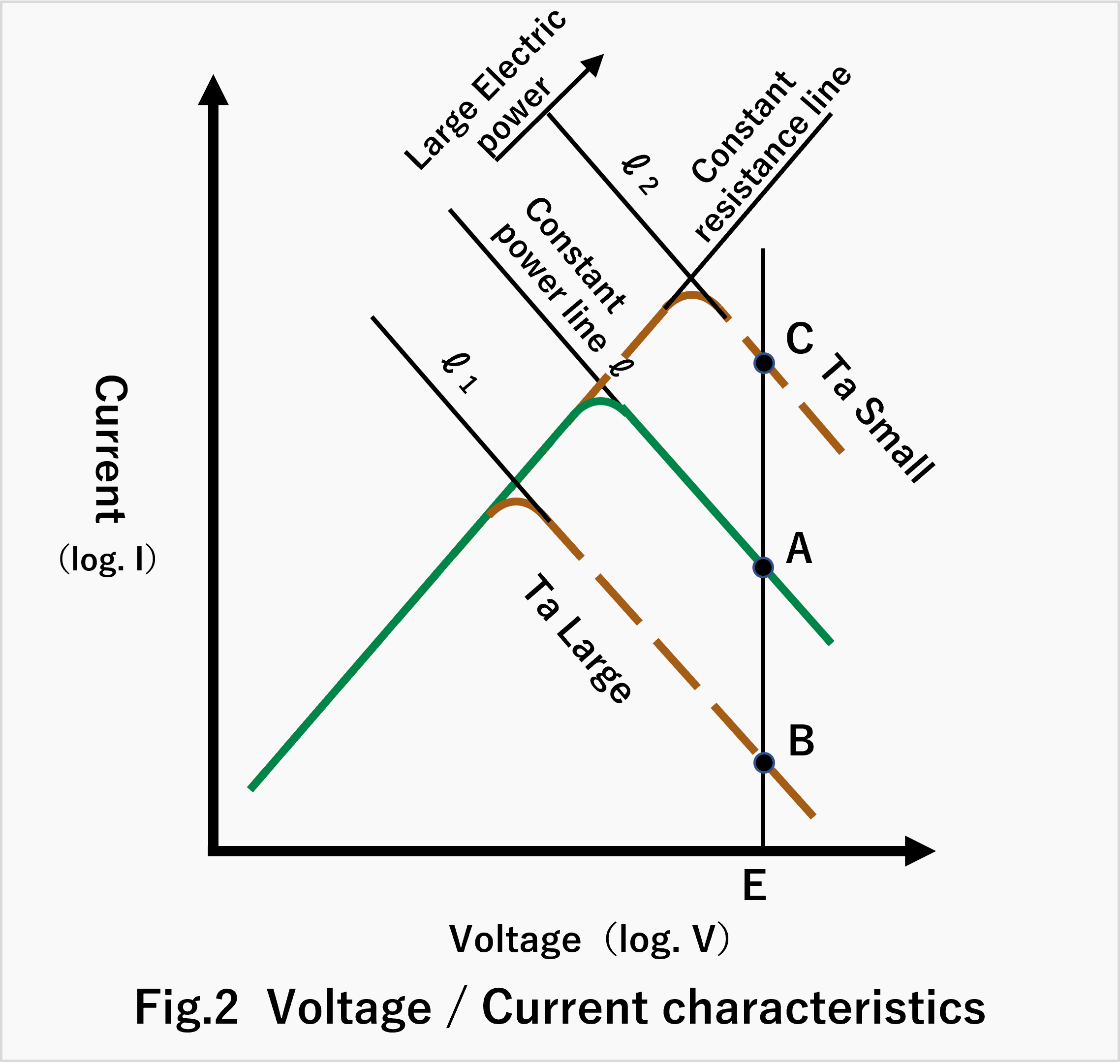
Fig.3 shows relation between the ambient Temperature and electric current
Fig.4 shows the relationship between PTC load magnitude and power.
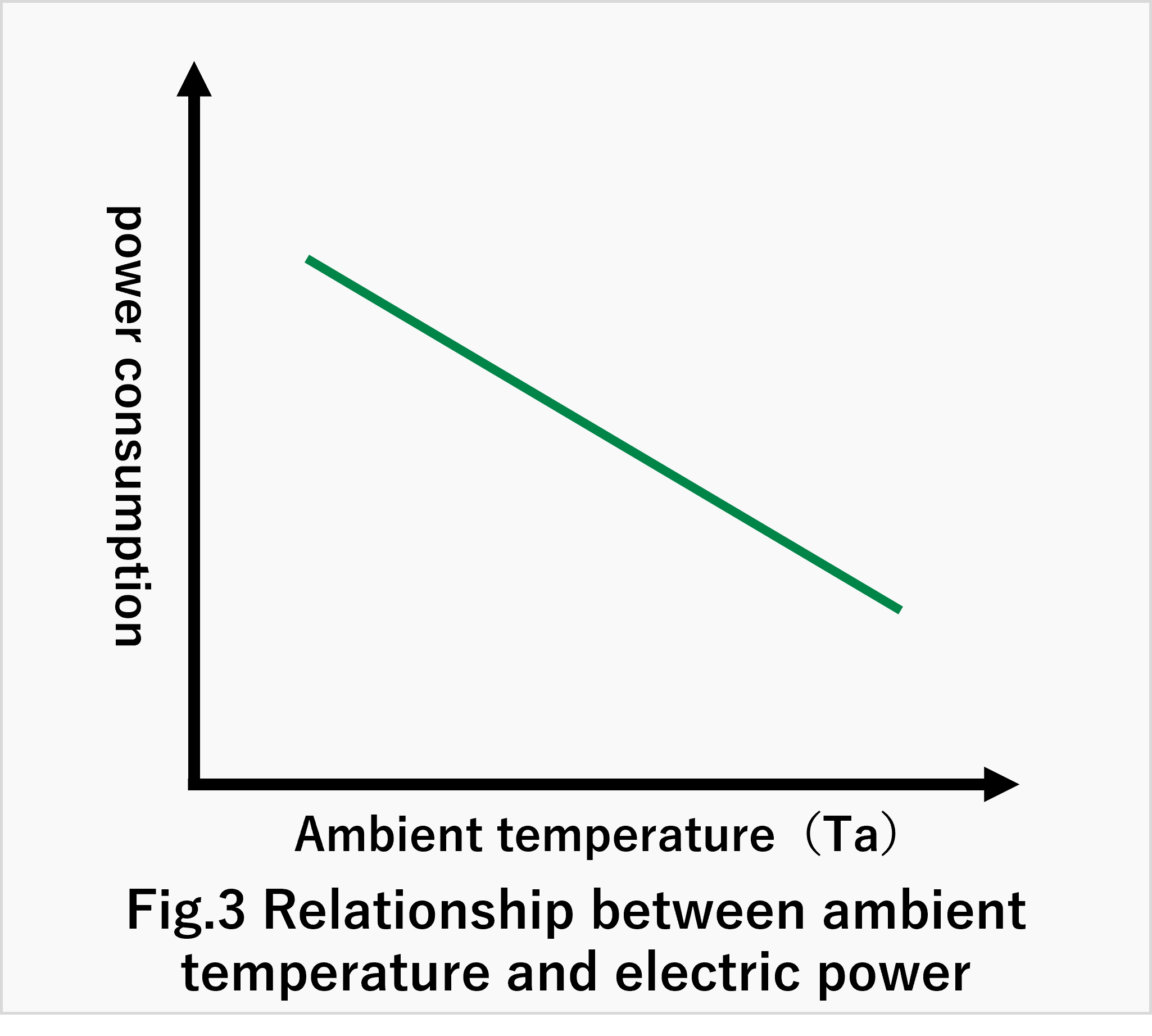
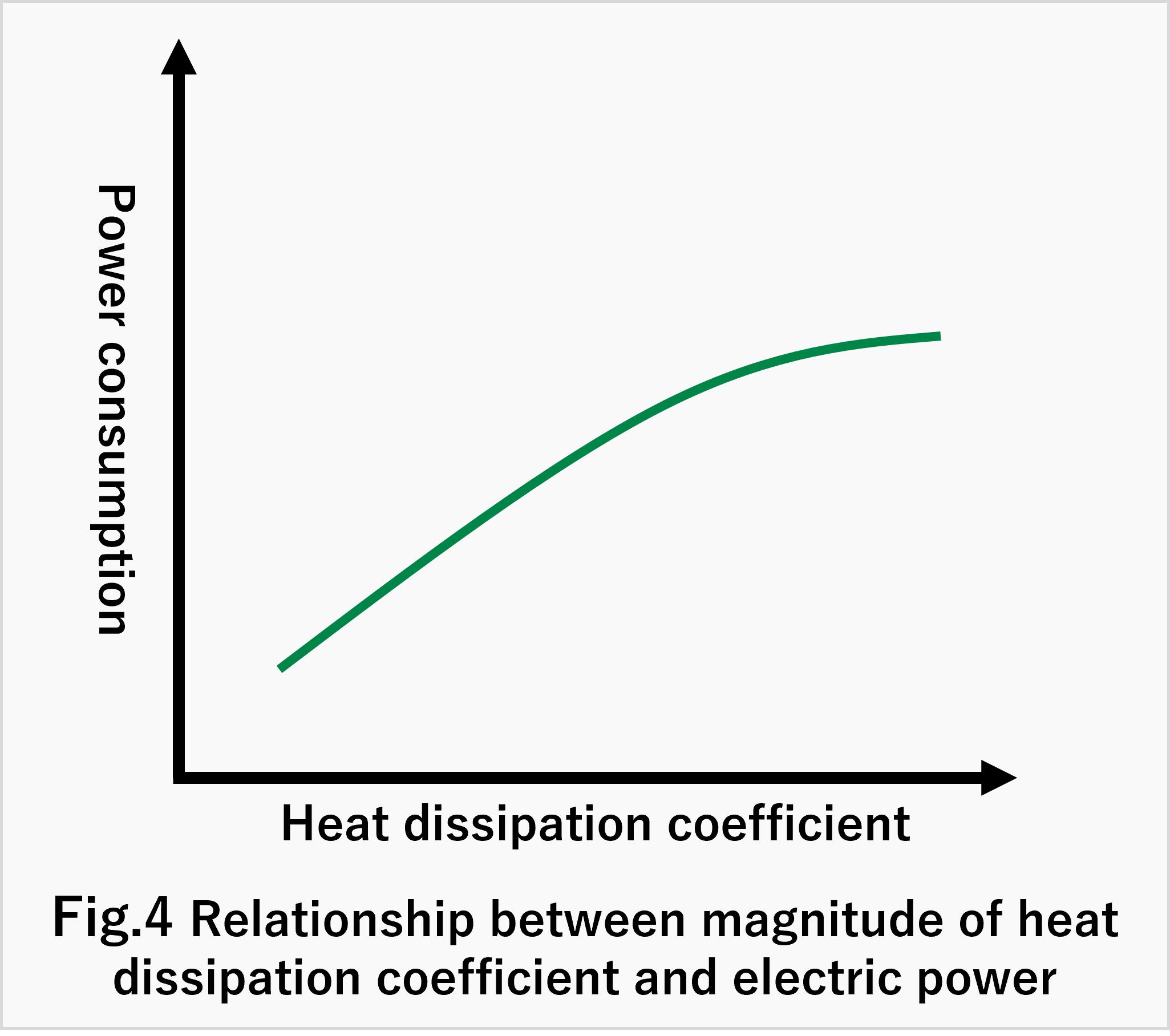
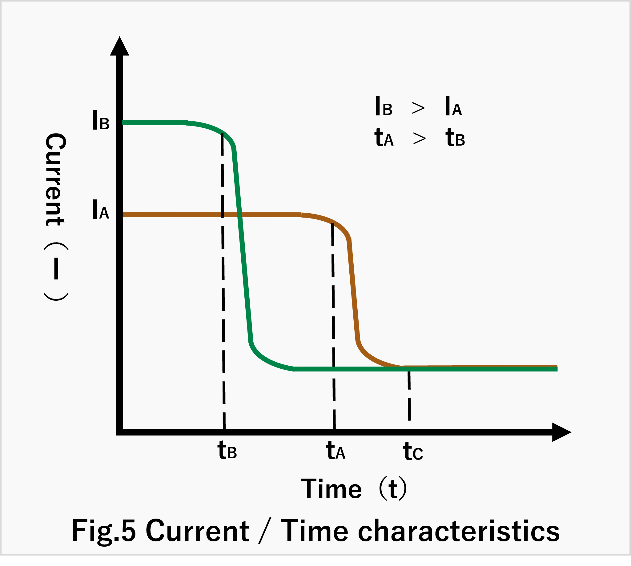
Fig.5 shows Ttime-current chararisics curve for smaller resistance(B) at room temperature(RT) and bigger resistance (A) at RT.
The rush current for B is bigger than the same for A but attenuation time for B is shorter then the sam for A.
Less than ta , heating time for B is shorter than the same for A.
But total energy at time tc is almost the same for A and B and Heating characterristics is not different from A to B.
In case the ambient Temperature is to be lower, etc. at Fig.5,the attenuation time wolud be longer and Current would be bigger.
Please find the following Table on example for PTC Heater
| Product Information on PTC Heater | |
|---|---|
| Hot Air Heater | To utilize Hot Air Heater Unit |
| For Liquid Heating | Liquid heating with Automatic Temperature control characteristics |
| Flat Panel Heater | Easy Fitting with direct heating panel |
| For Anti Freezing | Anti Freezing for Cold area |
| For Anti Fogging | Anti Fogging for Lens of Camera |